
2013/6/28 HOME
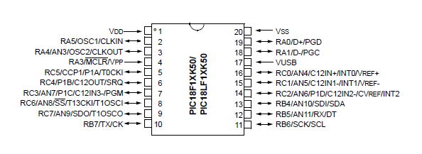
PIC18F14K50でアンテナローテータエモト103LBのコントローラーを作ってみました。

回路図 上部の6Pソケットはオンボード書込み用のICSPソケットです。使用しない場合は不要
江本103LBは0Vから6Vの電圧がアンテナの方向により出てきます。コントローラーをそのまま使う場合はソケットの4番5番間の電圧を測って表示すればOKです。
制作したものは5Vの電源とPIC18F14K50を使って409フルスケールの電圧計です。アンテナを360度の位置にまわして基盤上のVRを調整して360表示にします。この状態でステッピングモーターがちょうど1回転するようプログラム内の値を変更してください。安価の小型ステッピングモーターは18度ステップ(1回転20ステップ)など少々粗すぎますのでギヤ内蔵モーターを使うかギヤなどで減速してなめらかな表示ができるように工夫してください。
7セグLED3桁で360度の角度表示/下部の突き出た棒が回転方向SWです。HFを行う方は世界地図を張ってください。私は430MHzですので日本地図です。7以外はほとんどグランドウエーブでQSOできました。指針は1㎜のステンレス線です。アンテナの方向がよく分かるようになりました。
裏面です。ステッピングモーター使用/分解能力を上げるためギヤーで減速して表示しています。大型コンデンサーは6μF、AC200V モーター回転用のコンデンサーです。
モーターコントロールICは TA7774F
面実装 チップ です。オークションで 30個 900円 で購入 を使用しました。
秋 月では2個300円 6線式のユニポーラステッピングモーターも中点線をフリーにして回せます。
バイポーラ駆動による1 チップモータドライバ(ブリッジドライバ2 組内蔵)
パワーセーブ機能、 スタンバイ機能を有する。
励磁切り替え時の貫通電流保護回路内蔵
入力TTL コンパチブル IN A、IN B、PS 端子
IO (START) 350mA (MAX.) : VS1 ENABLE 時
IO (HOLD) 100mA (MAX.) : VS2 ENABLE 時
ピンのピッチは1mmですが、私のCNCの切削可能最小ピッチです。
放熱はピンを使って基板に逃がすタイプですのでパターンを大きくとって半田たっぷり盛って放熱します。
新たにモーターを購入する場合は秋月のギヤ付のモーターを購入してください。http://akizukidenshi.com/catalog/g/gP-05710/ @250 0.75度 ステップです。
タイマー1を使用して約10分位回転がない場合に現在の指針の位置をEEPROMに書き込んでいます。アンテナを回転させた後しばらくたってから電源を切ってください。次回の電源ONでEEPROMを読みだして指針の位置としています。デジタル角度表示と指針がずれた場合には手動で指針を回して合わせています。電源ON時に指針を回して0点調整をするなど色々な方法があると思いますが、現在はハードウエアーを簡単にするためこうしました。その都度現在 値をEEPROMに書き込んでも良いのですが、EEPROMには書込み回数の制限が有ります。
PICのAD変換は何度作っても最下位桁が安定しません。揺らぎはPICのクロックによってノイズ発生と思われます。他の方はどうしているのかあまり発表がありません。データーシートを読んだところスリープ(SLEEP)モードによる計測機能が有る事が解りました。AD測定中はPICの他の動作を止めて測定終了後に割り込みで復帰する方法です。次回は研究してみます。
2013/09/16 指針の現在値をEEPROMに保存していましたが、どうもうまくいかないので電源がONになったときに0点を確認する方式に変更しました。
歯車部分に穴を開けて原点を確認する方法に変更しました。
中央の黒いセンサー(フォトセンサー)で検出します。発光ダイオードの電流制限抵抗は1.5KΩを使用して薄く光らせています。プラ歯車は光を通過させるため!
動画による確認 http://youtu.be/Nm5QsaKDWCU
プログラム、回路図を変更しました。電圧入力はRC7 センサー入力はRA3 に変更。
/* ローテーター指示器 360°デジタル&アナログ
*PIC18F14K50 Created on 2013/05/01, 12:23
*/
#include <stdio.h>
#include <stdlib.h>
#include <xc.h>
#define _XTAL_FREQ 8000000
#pragma config CPUDIV = NOCLKDIV// CPU System Clock Selection bits (No CPU
System Clock divide)
#pragma config USBDIV = OFF // USB Clock Selection bit (USB clock comes directly
from the OSC1/OSC2 oscillator block; no divide)
#pragma config FOSC = IRC // Oscillator Selection bits (Internal RC oscillator)
#pragma config PLLEN = OFF // 4 X PLL Enable bit (PLL is under software control)
#pragma config PCLKEN = OFF // Primary Clock Enable bit (Primary clock is under
software control)
#pragma config FCMEN = OFF // Fail-Safe Clock Monitor Enable (Fail-Safe Clock
Monitor disabled)
#pragma config IESO = OFF // Internal/External Oscillator Switchover bit
(Oscillator Switchover mode disabled)
#pragma config PWRTEN = ON // Power-up Timer Enable bit (PWRT enabled)
#pragma config BOREN = OFF // Brown-out Reset Enable bits (Brown-out Reset
disabled in hardware and software)
#pragma config BORV = 19 // Brown-out Reset Voltage bits (VBOR set to 1.9 V
nominal)
#pragma config WDTEN = OFF // Watchdog Timer Enable bit (WDT is controlled by
SWDTEN bit of the WDTCON register)
#pragma config WDTPS = 32768 // Watchdog Timer Postscale Select bits (1:32768)
#pragma config HFOFST = OFF // HFINTOSC Fast Start-up bit (The system clock is
held off until the HFINTOSC is stable.)
#pragma config MCLRE = OFF // MCLR Pin Enable bit (RA3 input pin enabled; MCLR
disabled)
#pragma config STVREN = OFF // Stack Full/Underflow Reset Enable bit (Stack
full/underflow will not cause Reset)
#pragma config LVP = OFF // Single-Supply ICSP Enable bit (Single-Supply ICSP
disabled)
#pragma config BBSIZ = OFF // Boot Block Size Select bit (1kW boot block size)
#pragma config XINST = OFF // Extended Instruction Set Enable bit (Instruction
set extension and Indexed Addressing mode disabled (Legacy mode))
#pragma config CP0 = OFF // Code Protection bit (Block 0 not code-protected)
#pragma config CP1 = OFF // Code Protection bit (Block 1 not code-protected)
#pragma config CPB = OFF // Boot Block Code Protection bit (Boot block not
code-protected)
#pragma config CPD = OFF // Data EEPROM Code Protection bit (Data EEPROM not
code-protected)
#pragma config WRT0 = OFF // Table Write Protection bit (Block 0 not
write-protected)
#pragma config WRT1 = OFF // Table Write Protection bit (Block 1 not
write-protected)
#pragma config WRTC = OFF // Configuration Register Write Protection bit
(Configuration registers not write-protected)
#pragma config WRTB = OFF // Boot Block Write Protection bit (Boot block not
write-protected)
#pragma config WRTD = OFF // Data EEPROM Write Protection bit (Data EEPROM not
write-protected)
#pragma config EBTR0 = OFF // Table Read Protection bit (Block 0 not protected
from table reads executed in other blocks)
#pragma config EBTR1 = OFF // Table Read Protection bit (Block 1 not protected
from table reads executed in other blocks)
#pragma config EBTRB = OFF // Boot Block Table Read Protection bit (Boot block
not protected from table reads executed in other blocks)
const unsigned char seg_d[16] = {
0x40, 0x79, 0x24, 0x30, 0x19, 0x12, 0x02, 0x58, 0x00, 0x18,
0x08, 0x03, 0x27, 0x21, 0x06, 0x0E };
const unsigned char scan[4] = {
0b11101111,0b11011111,0b10111111,0b01111111};
const unsigned char md[4] = {
0b00110000,0b00100000,0b00000000,0b00010000};
unsigned char digit_no=0,dsp_buf[4]={0,0,0,0},e0,e1,e2;
unsigned int temp1,t2,mn,ma,dsp_cnt;
int n,mp,i;
void main(){
OSCCON= 0b01101010; //8MHz 選択
TRISA=0b11001111;TRISB=0b00000000;TRISC=0b10000000;
PORTA=0b00000000;PORTB=0b11111111;PORTC=0b11111111;
ADCON1= 0b00001000; //基準電圧FVR
ADCON2= 0b10111010; //右ADFM1,ACCQT111ADCS/32
REFCON0=0b10100000; //FVR 2.048V
ANSELH= 0b00000010; ANSEL=0; //RC7アナログ
ADCON0= 0b00100101; //RC7,ADON
RABPU=0;WPUA3=1; //pulup on
__delay_ms(50);
while (RA3=1) {if(--mp<0) mp=3;PORTA=md[mp];__delay_ms(5);}
mn=0;
while(1){
PORTB = 0b11111111; //全桁消灯
__delay_us(100);
GODONE = 1;
while(GODONE) {} // A/D変換済?
dsp_cnt=ADRESL+(ADRESH*256);
temp1=dsp_cnt <<2 ; //4096フルスケール
ma=(dsp_cnt<<6)/137; //モーター.ギヤに合わせる
if(mn>ma){mn--;if(--mp<0) mp=3;}//moter 回転
if(mn<ma){mn++;if(++mp>3) mp=0;}//moter 逆転
PORTA=md[mp];
n = 1000; // 4桁の10進数に変換
for(i=3;i>=0;i--){
t2 = temp1/n; // 千、百、十、一の個数を計算
dsp_buf[i] = (unsigned char)t2;// 表示バッファーに代入
temp1 = temp1 % n; // 余りを求める
n /= 10;
}
for (digit_no=0;digit_no<4;digit_no++){
PORTB = 0b11111111; //全桁消灯
PORTC = seg_d[dsp_buf[digit_no]] ;//7セグDATA出力
PORTB = (scan[digit_no]) ; // 走査ビット出力
__delay_ms(4);
}
}
}