
home 2013/07/10
AD変換のちらつきを無くすべく実験をしてみました。
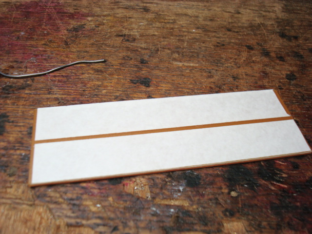
プリント基板の切り出し
裏に両面テープでCNCに貼り付け
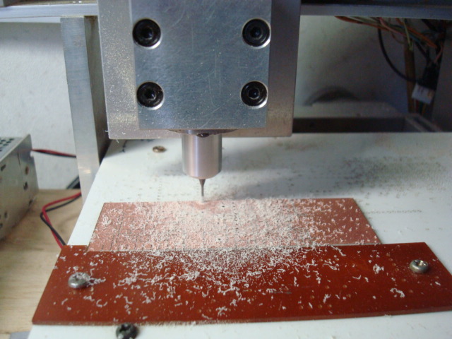
自作CNCで基盤切削 写真は穴あけ中です。
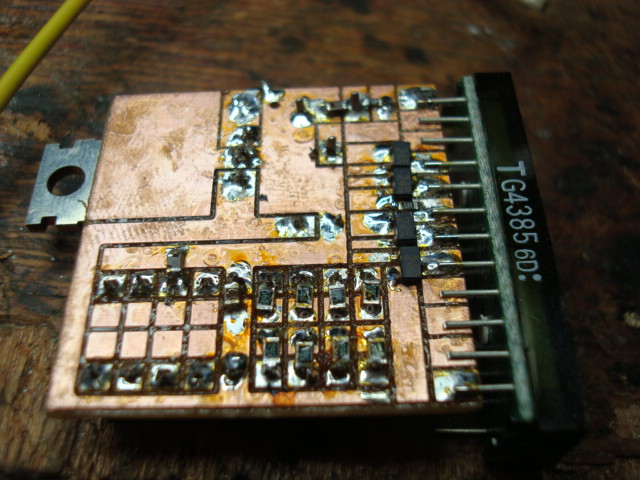
部品取り付け中
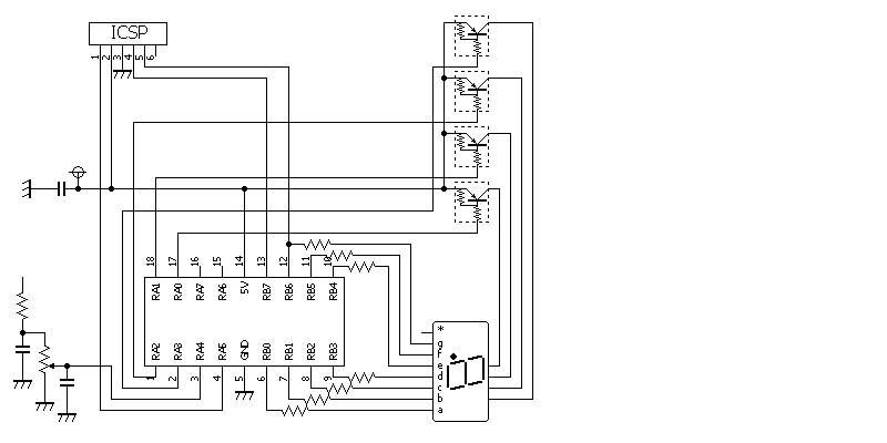
入力電圧のノイズを減らすためコンデンサーの付加、入力4番端子周りの配慮、測定は電圧落ち着いてから、調整VRは1KΩ等
使用7SEG LEDは型番表示部を下にして正面から見て次のようになっています。
-AGFCEDB-P-- 全部で24本足です。(TG4385というLEDですが規格表が検索できない)
---43P21----


ノイズに注意して作ってみました。SLEPP命令を使ってみようかと思ったのですが、何かうまくいかず!
普通の変換でも最下行のちらつきがなくなってしまいました。
http://youtu.be/n8-WgGZkPUg 動画で確認
/*
*PIC16F88 AD SLEEP Created on 2013/07/01 10bit A/D 20Vスケール電圧計 MPALBX XC8
*/
#include <stdio.h>
#include <stdlib.h>
#include <xc.h>
#define _XTAL_FREQ 8000000
#pragma config FOSC = INTOSCIO // Oscillator Selection bits (INTRC oscillator;
port I/O function on both RA6/OSC2/CLKO pin and RA7/OSC1/CLKI pin)
#pragma config WDTE = OFF // Watchdog Timer Enable bit (WDT disabled)
#pragma config PWRTE = ON // Power-up Timer Enable bit (PWRT enabled)
#pragma config MCLRE = OFF // RA5/MCLR/VPP Pin Function Select bit (RA5/MCLR/VPP
pin function is digital I/O, MCLR internally tied to VDD)
#pragma config BOREN = OFF // Brown-out Reset Enable bit (BOR disabled)
#pragma config LVP = OFF // Low-Voltage Programming Enable bit (RB3/PGM pin has
PGM function, Low-Voltage Programming enabled)
#pragma config CPD = OFF // Data EE Memory Code Protection bit (Code protection
off)
#pragma config WRT = OFF // Flash Program Memory Write Enable bits (Write
protection off)
#pragma config CCPMX = RB0 // CCP1 Pin Selection bit (CCP1 function on RB0)
#pragma config CP = OFF // Flash Program Memory Code Protection bit (Code
protection off)
#pragma config FCMEN = ON // Fail-Safe Clock Monitor Enable bit (Fail-Safe Clock
Monitor enabled)
#pragma config IESO = ON // Internal External Switchover bit (Internal External
Switchover mode enabled)
const unsigned char seg_d[16] = {
0x3F, 0x06, 0x5B, 0x4F, 0x66, 0x6D, 0x7D, 0x27, 0x7F, 0x67,
0x77, 0x7C, 0x58, 0x5E, 0x79, 0x71 };
const unsigned char scan[4] = {
0b00000001,0b00000010,0b00000100,0b00001000};
unsigned char digit_no=0,dsp_buf[4]={0,0,0,0},t;
unsigned int temp1,t2,dsp_cnt;
int n,i;
void lout(void);
void main(){
OSCCON= 0b01111000; //8MHz 選択
TRISA=0b11110000;TRISB=0b00000000;
PORTA=0b00000000;PORTB=0b00000000;
ADCON1= 0b11000000; //基準電圧VDD,VSS
ANSEL= 0b00010000; //RC4アナログ
ADCON0= 0b00100001; //RC4,ADON
while(1){
ADIF=0; //割込みFクリヤ
ADIE=1; //割込み許可
PEIE=1; //周辺割込み許可
__delay_us(10);
GO = 1; // A/D変換開始
// SLEEP();
while(GO){}
dsp_cnt=ADRESL+(ADRESH*256);
temp1=dsp_cnt<<1; //2000フルスケールニする
lout();
}
}
void lout(void){
n = 1000; // 4桁の10進数に変換
for(i=3;i>=0;i--){
t2 = temp1/n; // 千、百、十、一の個数を計算
dsp_buf[i] = (unsigned char)t2;// 表示バッファーに代入
temp1 = temp1 % n; // 余りを求める
n /= 10;
}
for (digit_no=0;digit_no<4;digit_no++){
PORTA = 0b11111111; //全桁消灯
PORTB = seg_d[dsp_buf[digit_no]] ; //7セグDATA出力
PORTA = (scan[digit_no]) ; // 桁ビット出力
__delay_ms(5);
}
}