 پ@پ@پ@
home پ@پ@2013/04/14
MPLAB X IDEپ@‚ج•×‹پAXC8پ@‚جCƒRƒ“ƒpƒCƒ‰پ[‚ًژg‚ء‚ؤ‚ف‚ـ‚µ‚½پB
ƒVƒ…ƒ~ƒŒپ[ƒ^پ[‚ًژg‚ء‚ؤ“®چى‚ًٹm‚©‚ك‚ـ‚µ‚½پB“®‚©‚ب‚©‚ء‚½ƒoƒO‚حپ@config ‚جگف’è‚إ‚µ‚½پBٹF‚³‚ٌ‚à‚و‚ٹm”F‚µ‚ؤ‚‚¾‚³‚¢پB
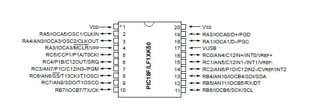
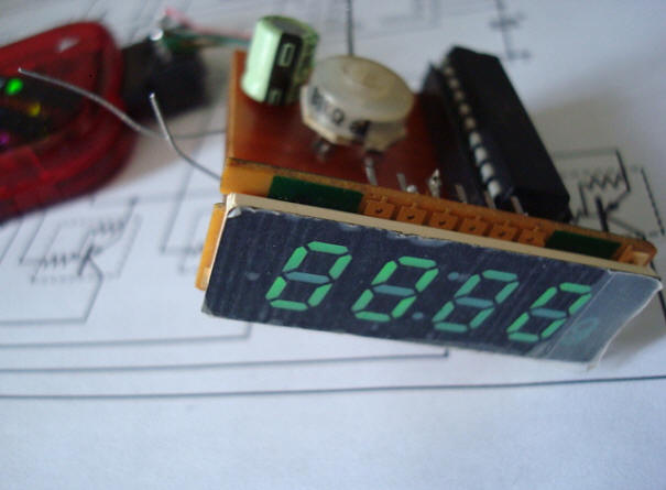
PIC18F14K50پ@‚ج10ƒrƒbƒgA/DƒRƒ“ƒoپ[ƒ^پ[‚ًژg—p‚µ‚ؤ“dˆ³Œv‚جچىگ¬‚إ‚·پB
پ@پ@پ@
پE‚Q‚Oƒsƒ“‚t‚r‚aƒtƒ‰ƒbƒVƒ…ƒ}ƒCƒNƒچƒRƒ“ƒgƒچپ[ƒ‰
پEƒiƒmƒڈƒbƒg‚w‚k‚oƒeƒNƒmƒچƒWپ[
پE‚t‚r‚a‚QپD‚OƒCƒ“ƒ^پ[ƒtƒFپ[ƒX“à‘
پE‚t‚r‚a—pƒfƒ…ƒAƒ‹ƒAƒNƒZƒX‚Q‚T‚UƒoƒCƒg‚q‚`‚l“à‘
پEƒvƒچƒOƒ‰ƒ€ƒپƒ‚ƒٹپF‚W‚jƒoƒCƒg
پE‚r‚q‚`‚lپF‚V‚U‚WƒoƒCƒg
پE‚d‚d‚o‚q‚n‚lپF‚Q‚T‚UƒoƒCƒg
پE‚hپ^‚nپFچإ‘ه‚P‚V‚ƒ‚ˆپ¦“à‚Pƒsƒ“پi‚l‚b‚k‚qپj‚حپAƒCƒ“ƒvƒbƒgگê—p
پ@ƒpƒbƒPپ[ƒWپF‚c‚h‚o‚Q‚Oƒsƒ“
پ@
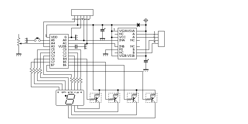
‰ٌکHگ}پ@پ@A0,A1‚ة‚آ‚ب‚ھ‚ء‚ؤ‚¢‚éIC‚ح–³ژ‹‚µ‚ؤ‚‚¾‚³‚¢پB
ژg‚ء‚ؤ‚ف‚ؤ‚جٹ´‘z‚حپ@ƒAƒZƒ“ƒuƒ‰پ[‚و‚èٹب’PپACŒ¾Œê‚ً•×‹‚·‚é•K—v‚ھ‚ ‚éپB
PIC‚»‚ج•¨‚جگف’è‚حچׂ©‚‚·‚é•K—v‚ ‚èپB
ژہچغ‚جƒvƒچƒOƒ‰ƒ€‚حچإŒم‚ج20چs’ِ“x‚ب‚ج‚إ‚·‚ھپA‚»‚ê‚ـ‚إ‰„پX‚ئPICژw’è‚ج•K—v‚ ‚èپB
/*
* File: newmain.c Author: A
*PIC18F14K50 Created on 2013/03/28, 12:23
*/
#include <stdio.h>
#include <stdlib.h>
#include <xc.h>
#pragma config USBDIV = OFF //;USB CLOCK SELECTION BIT
#pragma config MCLRE = OFF //;MCLR PIN ENABLE BIT
#pragma config IESO = OFF //;Internal/External
Oscillator Switchover bit
#pragma config FCMEN = OFF //;Fail-Safe Clock Monitor Enable bit
#pragma config FOSC = IRC //;OSCILLATOR SELECTION BITS
#pragma config PWRTEN = ON //;Power-up Timer Enable bit
#pragma config PLLEN = OFF //;X PLL ENABLE
BIT(OSCILLATOR MULTIPLIED BY 4)
#pragma config PCLKEN = OFF //;PRIMARY CLOCK ENABLE BIT
#pragma config BOREN = OFF //;Brown-out Reset Enable
bits
#pragma config LVP = OFF //;Single-Supply ICSP Enable
bit
#pragma config CPUDIV=NOCLKDIV //;CPU SYSTEM CLOCK SELECTION BIT
#pragma config CP0 = OFF //;Code Protection bit
#pragma config CP1 = OFF //;Code Protection bit
#pragma config CPD = OFF //;Data EEPROM Code Protection
bit
#pragma config CPB = OFF //;Boot Block Code Protection
bit
#pragma config WDTEN = OFF //;Watchdog Timer Enable bit
#pragma config HFOFST = OFF,STVREN = OFF,BBSIZ = OFF,XINST = OFF
#pragma config EBTR0 = OFF,EBTR1 = OFF,EBTRB = OFF
#define _XTAL_FREQ 8000000
const unsigned char seg_data[16] = {0x40, 0x79, 0x24, 0x30, 0x19, 0x12, 0x02,
0x58, 0x00, 0x18,0x08, 0x03, 0x27, 0x21, 0x06, 0x0E };
const unsigned char scan[4] = { 0b11101111,0b11011111,0b10111111,0b01111111};
unsigned char digit_no; // •\ژ¦‘–چ¸Œ…ژw’è
unsigned char dsp_buf[4]={0,0,0,0}; // •\ژ¦ƒoƒbƒtƒ@پ[
int dsp_cnt;
// •\ژ¦—pƒJƒEƒ“ƒg
void main()
{
OSCCON = 0b01101010 ; //8MHz ‘I‘ً
TRISA = 0b11111111;
TRISB = 0b00000000;
TRISC = 0b00000000;
PORTA = 0x00;
// ƒ|پ[ƒgڈ‰ٹْ‰»پB
PORTB = 0b11111111; //‘SŒ…ڈء“”
PORTC = 0b11111111; // ƒ|پ[ƒgڈ‰ٹْ‰»پB
digit_no = 0;
// ‘–چ¸Œ…No‚ًLSD‚ةڈ‰ٹْ‰»
dsp_cnt = 0;
// •\ژ¦ƒJƒEƒ“ƒ^‚ًڈ‰ٹْ‰»
unsigned int temp1,temp2; // 10گiگ”•دٹ·‚ةژg—p
int i;
// 10گiگ”•دٹ·‚ةژg—p
int n;
// 10گiگ”•دٹ·‚ةژg—p
ADCON1 = 0b00001000; //PVCFG 10 NVCFG 00
ADCON2 = 0b10111111; //‰EADFM1,ACCQT111ADCS111(FRC)
REFCON0= 0b10100000; //FVR 2.048V
ANSELH = 0b00000000 ; //ana off
ANSEL = 0b00001000 ; //RA4ƒAƒiƒچƒO ANSELH=0;
ADCON0 = 0b00001111; //RA4,ADON •دٹ·ٹJژn
while(1){
while(GODONE){ }
// A/D•دٹ·چد‚ف‚ب‚ç
dsp_cnt =ADRESL+(ADRESH*256) ; //
GODONE = 1;
//ژں‚ج A/D•دٹ·ٹJژn
temp1 = dsp_cnt;
// dsp_cnt‚ً4Œ…‚ج10گiگ”‚ة•دٹ·
n = 1000;
for(i = 3; i >= 0; i--){
temp2 = temp1 / n; //
گçپA•SپAڈ\پAˆê‚جŒآگ”‚ًŒvژZ
dsp_buf[i] = (unsigned char)temp2; // •\ژ¦ƒoƒbƒtƒ@پ[‚ة‘م“ü
temp1 = temp1 % n; // —]‚è‚ً‹پ‚ك‚é
n /= 10;
}
__delay_ms(5) ;
PORTB = 0b11111111; //‘SŒ…ڈء“”
PORTC = seg_data[dsp_buf[digit_no]] ;//7¾¸قDATAڈo—ح
PORTB = (scan[digit_no]) ; // ‘–چ¸ƒrƒbƒgڈo—ح
if(++digit_no == 4){digit_no = 0;} // •\ژ¦Œ…‚ً1Œ…–ع‚ةگف’è
}
}
پ@
ƒoƒO‚ ‚ء‚½‚çکA—چ‚µ‚ؤ‚‚¾‚³‚¢پB