
home 2013/07/25
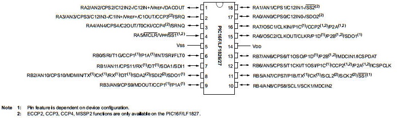
PICの手持ちがなくなったので新しく購入しました。どうせ買うなら新型が良いと!秋月で 16F1823 が \90 と格安ですが IOピンが使いにくそうで \110 の PIC16F1827 にしました。
PIC16F1827を使ってみました。これは8ビット単位で2組のIOがあり使いやすそうです。
ナノワットXLPテクノロジーによる超低消費電力
・プログラムメモリ:4Kワード
・RAM:384バイト
・EEPROM:256バイト
・I/O:最大16本
・ADコンバータ:10ビットx12ch
・コンパレータ:2ch
・タッチセンサ入力(CapSense):12ch
・タイマー:8ビットx4,16ビットx1
・動作クロック:32MHz(最大)
・電源電圧:1.8V(16MHz MAX)〜5.5V(32MHz MAX)
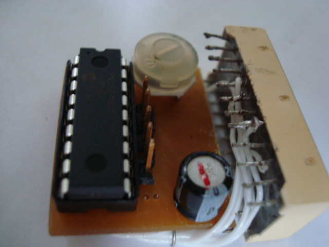
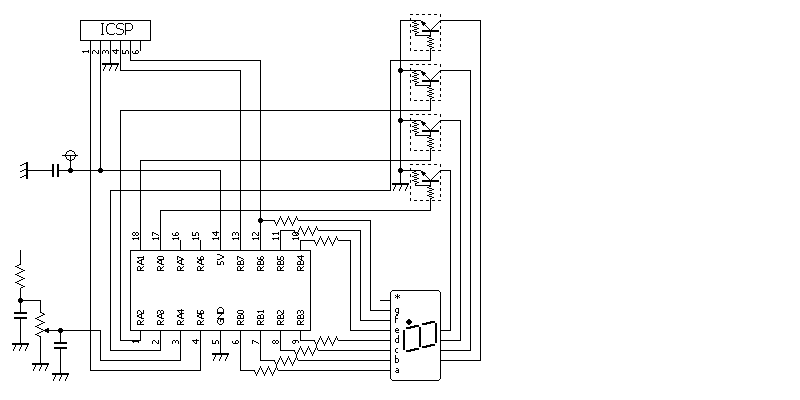
カソードコモン7SEG LEDを使用しました。ジャンクからの取り外し品
プログラム書き込み中
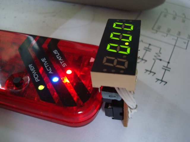
ほとんどプログラムの変更もなく動きました。20.48Vフルスケールの電圧計です。
/* File:
1827AD.c
* Author: vPro
* Created on 2013/07/27, 5:55
*/
#include <xc.h>
#include <stdio.h>
#include <stdlib.h>
#pragma config FOSC = INTOSC // Oscillator Selection (INTOSC oscillator: I/O
function on CLKIN pin)
#pragma config WDTE = OFF // Watchdog Timer Enable (WDT disabled)
#pragma config PWRTE = ON // Power-up Timer Enable (PWRT enabled)
#pragma config MCLRE = OFF // MCLR Pin Function Select (MCLR/VPP pin function is
digital input)
#pragma config CP = OFF // Flash Program Memory Code Protection (Program memory
code protection is disabled)
#pragma config CPD = OFF // Data Memory Code Protection (Data memory code
protection is disabled)
#pragma config BOREN = OFF // Brown-out Reset Enable (Brown-out Reset disabled)
#pragma config CLKOUTEN = OFF // Clock Out Enable (CLKOUT function is disabled.
I/O or oscillator function on the CLKOUT pin)
#pragma config IESO = OFF // Internal/External Switchover (Internal/External
Switchover mode is disabled)
#pragma config FCMEN = OFF // Fail-Safe Clock Monitor Enable (Fail-Safe Clock
Monitor is disabled)
#pragma config WRT = OFF // Flash Memory Self-Write Protection (Write protection
off)
#pragma config PLLEN = OFF // PLL Enable (4x PLL disabled)
#pragma config STVREN = OFF // Stack Overflow/Underflow Reset Enable (Stack
Overflow or Underflow will not cause a Reset)
#pragma config BORV = LO // Brown-out Reset Voltage Selection (Brown-out Reset
Voltage (Vbor), low trip point selected.)
#pragma config LVP = OFF // Low-Voltage Programming Enable (High-voltage on MCLR/VPP
must be used for programming)
#define _XTAL_FREQ 1000000
const unsigned char seg_d[16] = {
0x3F, 0x06, 0x5B, 0x4F, 0x66, 0x6D, 0x7D, 0x27, 0x7F, 0x67,
0x77, 0x7C, 0x58, 0x5E, 0x79, 0x71 };
const unsigned char scan[4] = {
0b00000001,0b00000010,0b00000100,0b00001000};
unsigned char digit_no=0,dsp_buf[4]={0,0,0,0};
unsigned int temp1,t2,dsp_cnt,t;
int n,i;
void lout(void);
int main(int argc, char** argv) {
OSCCON= 0b01011010; //1MHz 選択
TRISA=0b11110000;TRISB=0b00000000;
PORTA=0b00000000;PORTB=0b00000000;
ANSELA= 0b00010000; //RC4アナログ
ADCON1= 0b11110011; //基準電圧
FVRCON= 0b11000010; //FVR 2.048V
ADCON0= 0b00010001; //RC4,ADON
while(1){
// ADIF=0; //割込みFクリヤ
// ADIE=1; //割込み許可
// PEIE=1; //周辺割込み許可
for(t=0;t<2;t++){}; //wait
GO = 1; // A/D変換開始
// SLEEP();
while(GO){}
dsp_cnt=ADRESL+(ADRESH*256);
temp1=dsp_cnt<<1; //2000フルスケールニする
lout();
}
return (EXIT_SUCCESS);
}
void lout(void){
n = 1000; // 4桁の10進数に変換
for(i=3;i>=0;i--){
t2 = temp1/n; // 千、百、十、一の個数を計算
dsp_buf[i] = (unsigned char)t2;// 表示バッファーに代入
temp1 = temp1 % n; // 余りを求める
n /= 10;
}
for (digit_no=0;digit_no<4;digit_no++){
PORTB = seg_d[dsp_buf[digit_no]] ; //7セグDATA出力
if(digit_no==3 && dsp_buf[3]==0) PORTA=0 ; // 4桁目0なら表示しない
else { PORTA = (scan[digit_no]);
for(t=0;t<80;t++){}; //wait
}
}
}